ภาพรวม (Overview)
แนะนำ (Introduction)
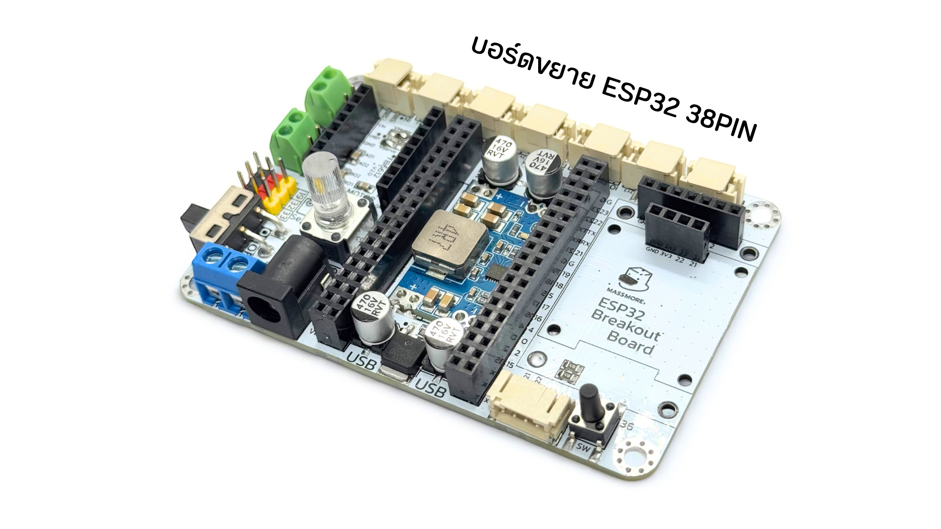
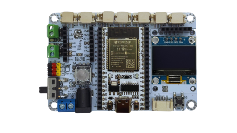
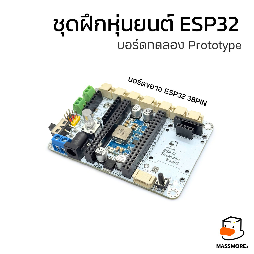
🔧 บอร์ดขยายหุ่นยนต์ ESP32 38PIN Breakout Board จาก Massmore
บอร์ดทดลองอัจฉริยะ เพื่อสร้างหุ่นยนต์และ IoT อย่างมืออาชีพ
พบกับ ESP32 Breakout Board ที่ออกแบบโดยทีมวิศวกรของ Massmore เพื่อยกระดับการเรียนรู้และการพัฒนาโปรเจกต์หุ่นยนต์ Arduino ให้ใช้งานง่าย ครบ จบในบอร์ดเดียว!
คุณสมบัติ (Features)
🚀 จุดเด่นที่คุณห้ามพลาด:
✅ รองรับ ESP32 (38 PIN) พร้อมใช้งานทันที เสียบได้พอดี!
🔌 DC IN (6–12V) พร้อมวงจร Step Down แปลงไฟให้เสถียรที่ 5V 5A เพื่อจ่ายไฟให้ทั้งระบบ
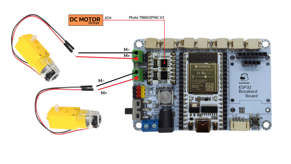
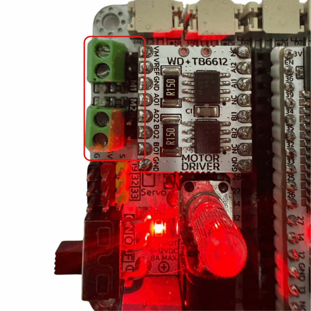
🎛 Driver มอเตอร์ รองรับ TB6612FNG หรือ Compatible
DC Motor 2 ช่อง (2CH)
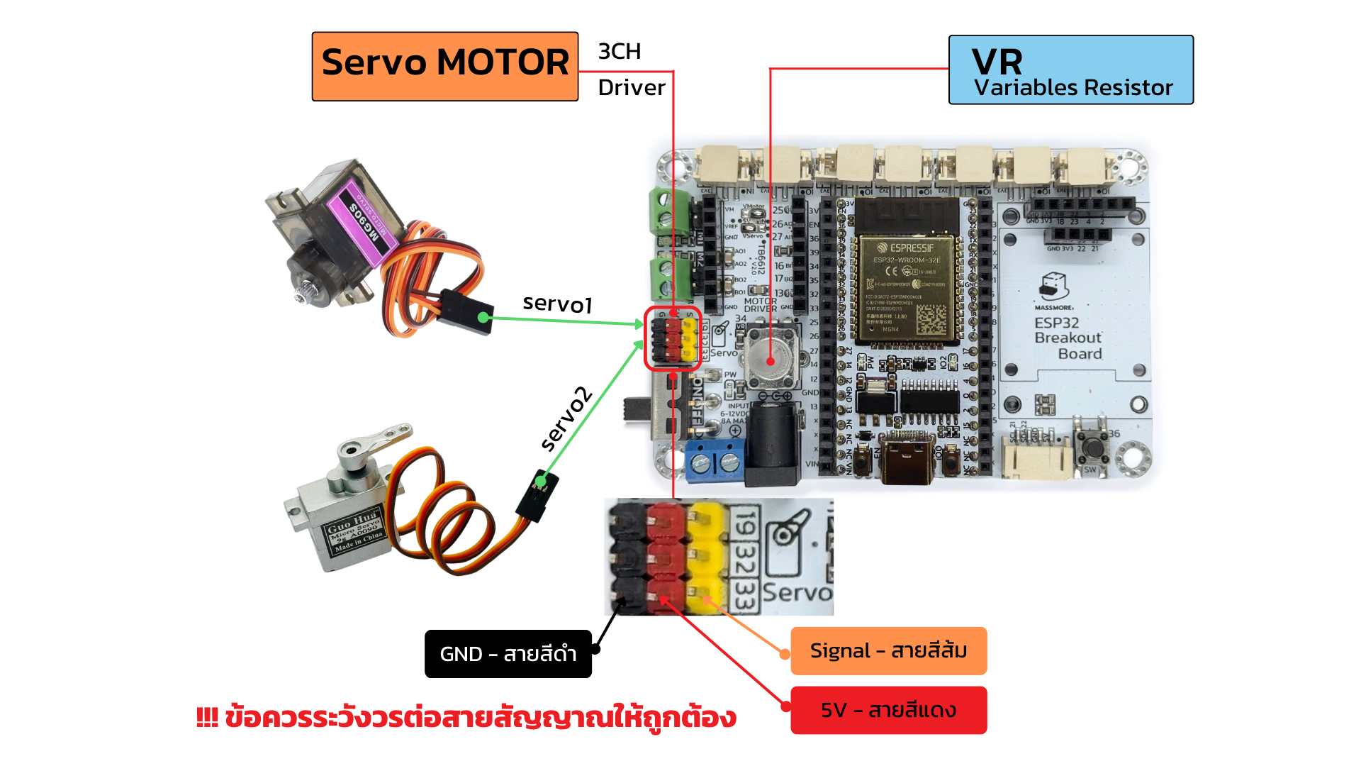
Servo Motor 3 ช่อง (3CH)
🔄 สวิตช์ ON-OFF ควบคุมไฟเลี้ยงสะดวกปลอดภัย
💡 ตัวต้านทานปรับค่าได้ (VR) สำหรับงานควบคุมที่ต้องการความแม่นยำ
🧠 GPIO พอร์ตเต็ม พร้อมใช้งานกับเซ็นเซอร์และอุปกรณ์เสริม
📺 พอร์ตจอแสดงผล (SCREEN) สำหรับต่อ OLED, LCD ฯลฯ
🔄 I²C Interface (PH2.0 4P) รองรับการเชื่อมต่อเซ็นเซอร์และโมดูลต่างๆ ผ่าน I2C ได้อย่างง่ายดาย
🔘 Switch พร้อมใช้งาน ติดตั้งง่าย ใช้ทดสอบโปรแกรมได้ทันที
🎯 เหมาะสำหรับใคร?
นักเรียน นักศึกษา ที่ต้องการ ชุดฝึกทดลอง Arduino / ESP32
Maker และผู้พัฒนา IoT ที่ต้องการบอร์ดขยายคุณภาพสูง
ผู้สอน STEM / Robotics ที่อยากให้การเรียนรู้สนุกและครอบคลุม
📦 ใช้ได้กับ:
หุ่นยนต์เดินตามเส้น / หุ่นยนต์เลี้ยวซ้ายขวา
ระบบสมาร์ทโฮม / สมาร์ทฟาร์ม
โปรเจกต์ IoT ทั่วไปที่ต้องการความเสถียรและง่ายในการต่อวงจร
ข้อมูลสินค้า (Spec Data)
ตารางข้อมูลสินค้า
| รายการ | รายละเอียด |
|---|---|
| รองรับบอร์ดหลัก | ESP32 (แบบ 38 ขา) |
| อินพุตไฟฟ้า (DC IN) | 6–12V (ผ่านแจ็ค 6.5 x 2.1mm) |
| วงจรจ่ายไฟ (Regulator) | Step Down 6–12V ➝ 5V 5A |
| เอาต์พุตไฟ 5V | รองรับโหลดสูงสุด 5A |
| ช่องควบคุม DC Motor | 2 ช่อง (2CH) รองรับ TB6612FNG หรือ Compatible |
| ช่องควบคุม Servo Motor | 3 ช่อง (3CH) |
| GPIO Header | 38 พิน (19 พินต่อฝั่ง) |
| I²C Connector | PH2.0 4P สำหรับเชื่อมต่อโมดูลภายนอก |
| พอร์ตต่อจอแสดงผล | สำหรับ OLED / LCD ฯลฯ |
| VR (Variable Resistor) | ตัวต้านทานปรับค่าได้ 1 ตัว |
| ปุ่มกด (Switch) | สำหรับทดสอบ / ควบคุมเบื้องต้น |
| สวิตช์เปิด-ปิด (ON-OFF Switch) | ตัดต่อไฟเลี้ยงจาก DC IN |
| ขนาดบอร์ด | ประมาณ 90 x 60 mm |
| วัสดุ PCB | FR4 คุณภาพสูง, เคลือบทองแดง 2 ด้าน |
| น้ำหนัก | ประมาณ 120 กรัม |
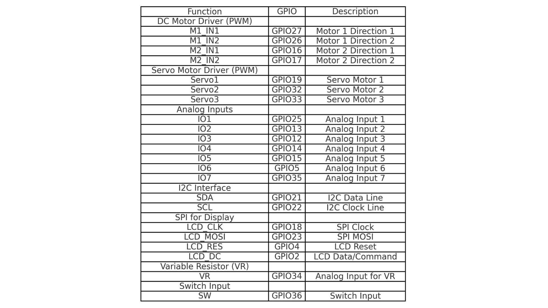
ตารางขาใช้งาน Pin table
ข้อมูลขนาดสินค้า
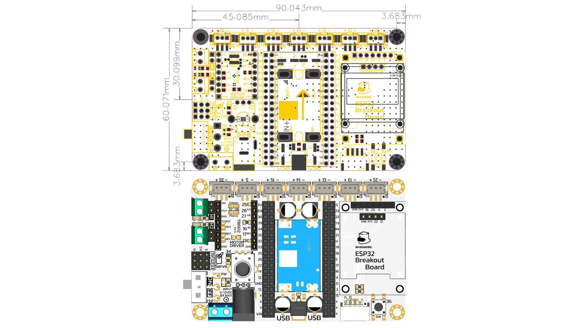
ข้อมูลบอร์ด (Onboard Resources)
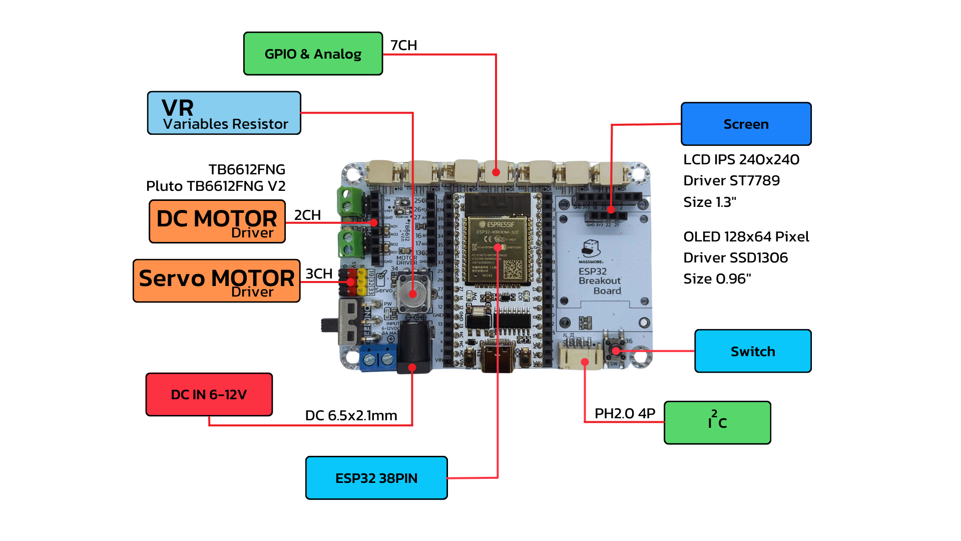
🟩 GPIO
พอร์ตขยายขา GPIO (General Purpose Input/Output) ของ ESP32 แบบครบทุกพิน
ใช้ต่อกับอุปกรณ์ภายนอก เช่น LED, เซ็นเซอร์, รีเลย์, ปุ่มกด ฯลฯ
รองรับทั้งโหมด Input และ Output
🔵 VR (Variable Resistor)
ตัวต้านทานปรับค่าได้
ใช้สำหรับทดลองหรืออ่านค่าจาก Potentiometer
เหมาะกับงานควบคุม เช่น ปรับความสว่าง, ควบคุมความเร็วมอเตอร์ หรือสร้างสัญญาณ Analog
🟧 DC Motor Driver (2CH)
ช่องต่อมอเตอร์กระแสตรง 2 ตัว
รองรับ TB6612FNG หรือ Compatible
รองรับการควบคุมทิศทางหมุน และความเร็วของมอเตอร์
🟧 Servo Motor Driver (3CH)
ช่องต่อเซอร์โวมอเตอร์ 3 ช่อง
ขั้วต่อแบบ JST พร้อมไฟเลี้ยงและสัญญาณ
ใช้ควบคุมมอเตอร์เซอร์โวในการหมุนตามองศาที่ต้องการ
🔴 ON-OFF Switch
สวิตช์ตัดต่อไฟหลักจาก DC IN
ใช้งานสะดวก ปลอดภัย ไม่ต้องถอดปลั๊กบ่อย
🔴 DC IN (6–12V)
แจ็คขนาด 6.5×2.1mm สำหรับรับไฟเลี้ยงจากอะแดปเตอร์
รองรับแรงดันอินพุต 6–12V
ป้อนพลังงานให้กับบอร์ดและอุปกรณ์ทั้งหมด
🔷 STEP Down (6–12V to 5V5A)
วงจรแปลงแรงดันจาก DC IN (6–12V) ลงเป็น 5V 5A
ใช้เลี้ยง ESP32 และอุปกรณ์อื่นอย่างเสถียร
จ่ายกระแสสูงเพียงพอสำหรับมอเตอร์และเซอร์โว
🔵 SCREEN (OLED/LCD)
พอร์ตสำหรับต่อจอแสดงผล เช่น OLED, LCD
ช่วยให้แสดงค่าข้อมูลต่าง ๆ ได้สะดวก
🔷 Switch (ปุ่มกด)
ปุ่มกดใช้งานได้ทันที เหมาะกับการทดสอบโปรแกรม
ใช้เป็นปุ่มควบคุมหุ่นยนต์หรือฟังก์ชันอื่น ๆ
🟩 I²C (PH2.0 4P)
พอร์ตสำหรับอุปกรณ์ที่ใช้โปรโตคอล I²C เช่น เซ็นเซอร์วัดอุณหภูมิ, จอ OLED, RTC ฯลฯ
ขั้วต่อแบบ PH2.0 4 พิน: VCC, GND, SDA, SCL
📌 หมายเหตุ:
ตรงกลางคือช่องเสียบ ESP32 (38 PIN) ซึ่งเป็น MCU หลักของบอร์ด โดยบอร์ดนี้ออกแบบมาให้พร้อมใช้งานกับ ESP32 ได้ทันที โดยไม่ต้องต่อวงจรซับซ้อนเพิ่มเติม
ตัวอย่างโปรแกรม (Example Arduino Code)
ตัวอย่างที่ 1 การควบคุมเซอร์โวมอเตอร์และ LED ด้วย ESP32 โดยใช้ ตัวต้านทานปรับค่าได้ (Potentiometer) และสวิตช์ (Switch)
ในบทความนี้ เราจะอธิบายการทำงานของโปรแกรมบนบอร์ด ESP32 ที่ใช้ควบคุมเซอร์โวมอเตอร์ 2 ตัว และไฟ LED ด้วย Potentiometer (VR) และสวิตช์ โดยแสดงข้อมูลทั้งหมดผ่านทาง Serial Monitor โปรแกรมนี้เหมาะสำหรับการเรียนรู้เบื้องต้นเกี่ยวกับการอ่านค่าจำเพาะจาก analog input และ digital input พร้อมการควบคุมอุปกรณ์ output อย่างเซอร์โวและ LED
อุปกรณ์ที่ใช้ในโปรเจกต์
บอร์ด ESP32 38PIN Massmore
เซอร์โวมอเตอร์ Servo motor 2 ตัว (รุ่นใดก็ได้)
Potentiometer (VR) Onboard
Push Button (SW) Onboard
LED Onboard
Arduino IDE Code
- อย่าลืมติดตั้ง Library ***ESP32Servo*** จากไฟล์บน Github
					#include <ESP32Servo.h>

#define VR_PIN 34      // ขาอ่านค่า VR (Potentiometer)
#define SW_PIN 36      // ขาอ่านค่าสวิตช์
#define LED_PIN 2      // ขา LED
#define SERVO1_PIN 19  // ขา Servo 1
#define SERVO2_PIN 32  // ขา Servo 2

Servo servo1, servo2;
bool ledState = false;
bool lastButtonState = HIGH;

void setup() {
    Serial.begin(115200);
    pinMode(VR_PIN, INPUT);
    pinMode(SW_PIN, INPUT_PULLUP);
    pinMode(LED_PIN, OUTPUT);

    servo1.attach(SERVO1_PIN);
    servo2.attach(SERVO2_PIN);
}

void loop() {
    // อ่านค่าจาก VR และแปลงเป็นองศา (0 - 180)
    int vrValue = analogRead(VR_PIN);
    int angle = map(vrValue, 0, 4095, 0, 180);

    // ควบคุมเซอร์โว
    servo1.write(angle);
    servo2.write(180 - angle);

    // อ่านค่าจากสวิตช์
    bool buttonState = digitalRead(SW_PIN);

    // เช็คการเปลี่ยนแปลงของปุ่มเพื่อทำ Toggle
    if (buttonState == LOW && lastButtonState == HIGH) {
        ledState = !ledState;
        digitalWrite(LED_PIN, ledState);
        delay(200); // กันสัญญาณกดเด้ง (Debounce)
    }
    lastButtonState = buttonState;

    // แสดงค่าผ่าน Serial Monitor
    Serial.print("VR Volume: ");
    Serial.print(vrValue);
    Serial.print(" | Servo Angle: ");
    Serial.print(angle);
    Serial.print(" | SW State: ");
    Serial.println(buttonState ? "HIGH" : "LOW");

    delay(100);
}
อธิบายการทำงานของโค้ด
1. การกำหนดขาเชื่อมต่อ
กำหนดขาเชื่อมต่อของแต่ละอุปกรณ์เข้ากับขา GPIO บน ESP32
					#define VR_PIN 34      // ขาอ่านค่า VR (Potentiometer)
#define SW_PIN 36      // ขาอ่านค่าสวิตช์
#define LED_PIN 2      // ขา LED
#define SERVO1_PIN 19  // ขา Servo 1
#define SERVO2_PIN 32  // ขา Servo 2
2. การตั้งค่าในฟังก์ชัน setup()
					void setup() {
    Serial.begin(115200);
    pinMode(VR_PIN, INPUT);
    pinMode(SW_PIN, INPUT_PULLUP);
    pinMode(LED_PIN, OUTPUT);

    servo1.attach(SERVO1_PIN);
    servo2.attach(SERVO2_PIN);
}
เริ่มต้น Serial Monitor เพื่อดูค่าผลลัพธ์
ตั้งค่าโหมดของขาอินพุตและเอาต์พุต
กำหนดให้เซอร์โวมอเตอร์แต่ละตัวทำงานกับขาที่กำหนด
3. การทำงานในลูปหลัก loop()
					int vrValue = analogRead(VR_PIN);
int angle = map(vrValue, 0, 4095, 0, 180);
อ่านค่าจาก VR (0 – 4095) แล้วแปลงให้เป็นองศา (0 – 180)
ส่งค่ามุมไปควบคุมเซอร์โวมอเตอร์
					servo1.write(angle);
servo2.write(180 - angle);
เซอร์โวตัวที่ 1 หมุนตามค่าที่ได้
เซอร์โวตัวที่ 2 หมุนสวนทาง (180 – ค่าเดิม)
4. การควบคุม LED ด้วยสวิตช์
					bool buttonState = digitalRead(SW_PIN);

if (buttonState == LOW && lastButtonState == HIGH) {
    ledState = !ledState;
    digitalWrite(LED_PIN, ledState);
    delay(200);
}
lastButtonState = buttonState;
เมื่อกดปุ่ม (สถานะจาก HIGH → LOW) จะสลับสถานะของ LED (เปิด/ปิด)
มีการหน่วงเวลาเล็กน้อย (debounce) เพื่อกันการสั่นของสัญญาณปุ่ม
5. การแสดงค่าผ่าน Serial Monitor
					Serial.print("VR Volume: ");
Serial.print(vrValue);
Serial.print(" | Servo Angle: ");
Serial.print(angle);
Serial.print(" | SW State: ");
Serial.println(buttonState ? "HIGH" : "LOW");
แสดงค่าที่อ่านได้จาก VR, มุมของเซอร์โว และสถานะของปุ่มบน Serial Monitor
สรุป
โค้ดนี้เป็นตัวอย่างที่ดีในการใช้ ESP32 ร่วมกับอุปกรณ์อินพุตและเอาต์พุตพื้นฐาน โดยเราสามารถ:
ควบคุมเซอร์โวแบบเรียลไทม์ด้วย VR
สลับเปิด/ปิดไฟ LED ด้วยปุ่ม
แสดงค่าทั้งหมดผ่าน Serial Monitor เพื่อการดีบั๊กหรือศึกษาพฤติกรรมของระบบ
หากคุณต้องการพัฒนาเพิ่มเติม เช่น เพิ่มการควบคุมผ่าน Wi-Fi หรือจอแสดงผล OLED ก็สามารถต่อยอดจากพื้นฐานนี้ได้เลย
ตัวอย่างที่ 2 การควบคุมมอเตอร์ 2CH พร้อมวิธีการตั้งค่า (ใช้งานกับไดร์ฟ Pluto TB6612FNG V2 ใช้ชิพ TB67H450FNG)
ในบทความนี้ เราจะอธิบายการทำงานของโปรแกรมบนบอร์ด ESP32 ที่ใช้ควบคุมดีซีมอเตอร์ Brush DC motor 2 ตัว โปรแกรมนี้เหมาะสำหรับการเรียนรู้เบื้องต้นเกี่ยวกับการควบคุมอุปกรณ์ Output DC motor
อุปกรณ์ที่ใช้ในโปรเจกต์
บอร์ด ESP32 38PIN Massmore
ดีซีมอเตอร์ Brush DC motor 2 ตัว (รุ่นใดก็ได้)
- บอร์ดขับมอเตอร์ TB6612FNG หรือ Pluto (รุ่นใดก็ได้)
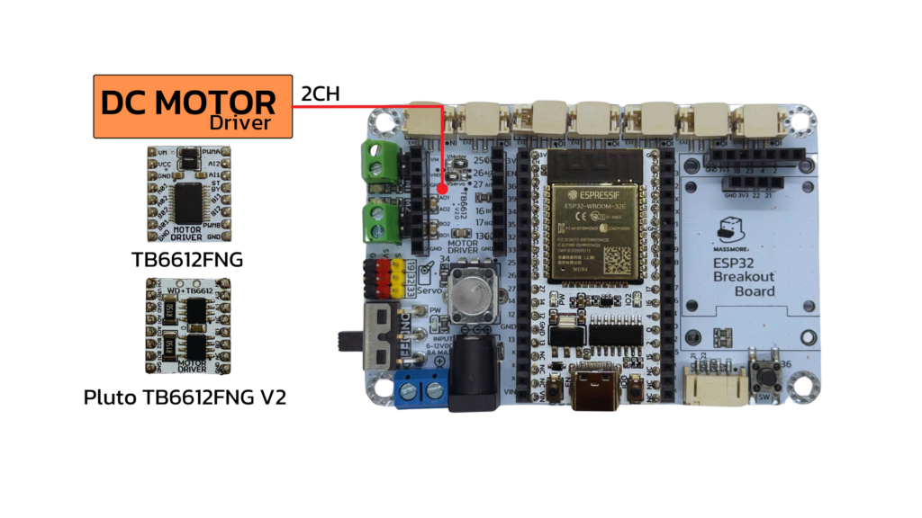
1. TB6612FNG – รุ่นยอดนิยม ใช้งานง่าย
| รายการ | รายละเอียด |
|---|---|
| โหมดควบคุม | PWM 2 ขา (PWMA, PWMB) + IN1, IN2 (4 ขา) |
| จำนวนมอเตอร์ | ขับได้ 2 ตัว (2CH) |
| แรงดันใช้งาน | 2.5V – 13.5V |
| กระแสสูงสุดต่อช่อง | 1.2A (สูงสุด 3.2A burst) |
| พินควบคุม | AIN1, AIN2, BIN1, BIN2 + PWMA, PWMB |
| เหมาะกับ | รถบังคับ, หุ่นยนต์ 2 ล้อ, โปรแกรมง่าย |
✅ ข้อดี:
ใช้งานง่าย เหมาะสำหรับผู้เริ่มต้น
ใช้พิน PWM ควบคุมเพียง 2 ขา
มีวงจรเบรกในตัว
2. TB67H450FNG (Pluto) – พลังสูง ทนทาน
| รายการ | รายละเอียด |
|---|---|
| โหมดควบคุม | PWM แยก 4 ขา (PWM1, PWM2, PWM3, PWM4) |
| จำนวนมอเตอร์ | ขับได้ 2 ตัว (2CH) |
| แรงดันใช้งาน | 4.5V – 28V |
| กระแสสูงสุด | 3.5A (สูงสุดถึง 5A burst) |
| พินควบคุม | IN1, IN2, IN3, IN4 |
| เหมาะกับ | มอเตอร์ใหญ่, หุ่นยนต์รับน้ำหนัก, แข่งขันหุ่นยนต์ |
✅ ข้อดี:
ทนกระแสสูง เหมาะกับมอเตอร์กินกระแสหนัก
มีระบบป้องกันกระแสเกิน / ความร้อน
ขับมอเตอร์ได้ลื่นแม่นยำ ควบคุมแรงบิดได้ดี
- ใช้พินควบคุมน้อย
Arduino IDE Code
โปรแกรมนี้เขียนด้วยภาษา Arduino โดยมีจุดประสงค์เพื่อ ควบคุมการทำงานของมอเตอร์ DC 2 ตัว ผ่านขา GPIO ของ ESP32 โดยใช้ PWM (Pulse Width Modulation) เพื่อควบคุมทิศทางและความเร็วของมอเตอร์
// Motor
int motor1Pin1 = 16;
int motor1Pin2 = 17;
int motor2Pin1 = 27;
int motor2Pin2 = 26;

// the setup routine runs once when you press reset:
void setup()
{
  Serial.begin(115200);
  delay(10);

  ledcAttachPin(motor1Pin1, 1); // assign RGB led pins to channels
  ledcAttachPin(motor1Pin2, 2);
  ledcAttachPin(motor2Pin1, 3);
  ledcAttachPin(motor2Pin2, 4);

  // Initialize channels
  // channels 0-15, resolution 1-16 bits, freq limits depend on resolution
  // ledcSetup(uint8_t channel, uint32_t freq, uint8_t resolution_bits);
  ledcSetup(1, 12000, 8); // 12 kHz PWM, 8-bit resolution
  ledcSetup(2, 12000, 8);
  ledcSetup(3, 12000, 8);
  ledcSetup(4, 12000, 8);

  Serial.print("Testing DC Motor...");
}
// void loop runs over and over again
void loop()
{
    // Stop the DC motor
  Serial.println("Motor stopped");
  ledcWrite(1, 0);
  ledcWrite(2, 0);
  ledcWrite(3, 0);
  ledcWrite(4, 0);
  delay(1000);
  // Move the DC motor forward at maximum speed
  Serial.println("Moving Forward");
  ledcWrite(1, 255);
  ledcWrite(2, 0);
  ledcWrite(3, 255);
  ledcWrite(4, 0);
  delay(3000);

  // Move DC motor backwards at maximum speed
  Serial.println("Moving Backwards");
  ledcWrite(1, 0);
  ledcWrite(2, 255);
  ledcWrite(3, 0);
  ledcWrite(4, 255);
  delay(3000);

  // Stop the DC motor
  Serial.println("Motor stopped");
  ledcWrite(1, 0);
  ledcWrite(2, 0);
  ledcWrite(3, 0);
  ledcWrite(4, 0);
  delay(1000);

  // Stop the DC motor
  Serial.println("Motor Speed+");
  ledcWrite(1, 100);
  ledcWrite(2, 0);
  ledcWrite(3, 100);
  ledcWrite(4, 0);
  delay(1000);

    // Stop the DC motor
  Serial.println("Motor Speed+");
  ledcWrite(1, 125);
  ledcWrite(2, 0);
  ledcWrite(3, 125);
  ledcWrite(4, 0);
  delay(1000);

    // Stop the DC motor
  Serial.println("Motor Speed+");
  ledcWrite(1, 200);
  ledcWrite(2, 0);
  ledcWrite(3, 200);
  ledcWrite(4, 0);
  delay(1000);


    // Stop the DC motor
  Serial.println("Motor Speed+");
  ledcWrite(1, 255);
  ledcWrite(2, 0);
  ledcWrite(3, 255);
  ledcWrite(4, 0);
  delay(1000);

}
อธิบายการทำงานของโค้ด
1. การกำหนดขาเชื่อมต่อ การตั้งค่าในฟังก์ชัน setup()
					int motor1Pin1 = 16;
int motor1Pin2 = 17;
int motor2Pin1 = 27;
int motor2Pin2 = 26;
กำหนดขา GPIO ที่ใช้ควบคุมมอเตอร์ 2 ตัว (แต่ละตัวใช้ 2 ขา – หมุนซ้าย/ขวา)
					ledcAttachPin(motor1Pin1, 1);
ledcAttachPin(motor1Pin2, 2);
ledcAttachPin(motor2Pin1, 3);
ledcAttachPin(motor2Pin2, 4);
ผูกขา GPIO กับ ช่องสัญญาณ PWM (channel) ของ ESP32 เพื่อส่งความถี่ PWM ไปควบคุมมอเตอร์
					ledcSetup(1, 12000, 8);
ledcSetup(2, 12000, 8);
ledcSetup(3, 12000, 8);
ledcSetup(4, 12000, 8);
กำหนดคุณสมบัติของ PWM:
ความถี่ 12 kHz
ความละเอียด 8 บิต (ค่าความแรง 0–255)
2. การทำงานในลูปหลัก loop()
ledcWrite(1, 0); ledcWrite(2, 0); ledcWrite(3, 0); ledcWrite(4, 0);
หยุดมอเตอร์ (Motor stopped) ส่งค่า 0 ทุกช่อง = มอเตอร์ไม่หมุน
3. การทำงานในลูปหลัก loop()
					ledcWrite(1, 255); ledcWrite(2, 0);
ledcWrite(3, 255); ledcWrite(4, 0);
หมุนเดินหน้า (Moving Forward) มอเตอร์ทั้ง 2 ตัวหมุนในทิศทางเดียวกัน เดินหน้าเต็มความเร็ว
					ledcWrite(1, 0); ledcWrite(2, 255);
ledcWrite(3, 0); ledcWrite(4, 255);
หมุนถอยหลัง (Moving Backwards) กลับทิศหมุนเพื่อถอยหลัง
					ledcWrite(1, 100); // ความเร็วระดับ 1
...
ledcWrite(1, 125); // ระดับ 2
...
ledcWrite(1, 200); // ระดับ 3
...
ledcWrite(1, 255); // เต็มสปีด
เพิ่มความเร็วทีละขั้น (Motor Speed+)
ทดสอบการปรับระดับความเร็วของมอเตอร์
ใช้เพื่อดูผลของ PWM ที่มีต่อความเร็วในการหมุน
- ตัวอย่างการทำงาน ไฟแสดงสถานะ LED ดับ = มอเตอร์หยุดหมุน
- ตัวอย่างการทำงาน ไฟแสดงสถานะ LED สีแดง = มอเตอร์หมุนไปข้างหน้า
- ตัวอย่างการทำงาน ไฟแสดงสถานะ LED สีเขียว = มอเตอร์หมุนไปข้างหลัง
สรุป
ใช้ PWM (Pulse Width Modulation) จาก ESP32 ควบคุมความเร็วของมอเตอร์
ใช้ 2 ขา GPIO ต่อมอเตอร์ 1 ตัว เพื่อกำหนดทิศทางการหมุน
สามารถ ควบคุมเดินหน้า ถอยหลัง และปรับระดับความเร็วได้
เหมาะกับการใช้งานร่วมกับ Driver เช่น TB6612FNG หรือ TB67H450FNG (Pluto) ที่รองรับการสั่งงานด้วย PWM
การใช้งานหน้าจอแสดงผล LCD 240x240 ST7789 และ หน้าจอ OLED 128x64 Pixel Driver SSD1306 Size 0.96"
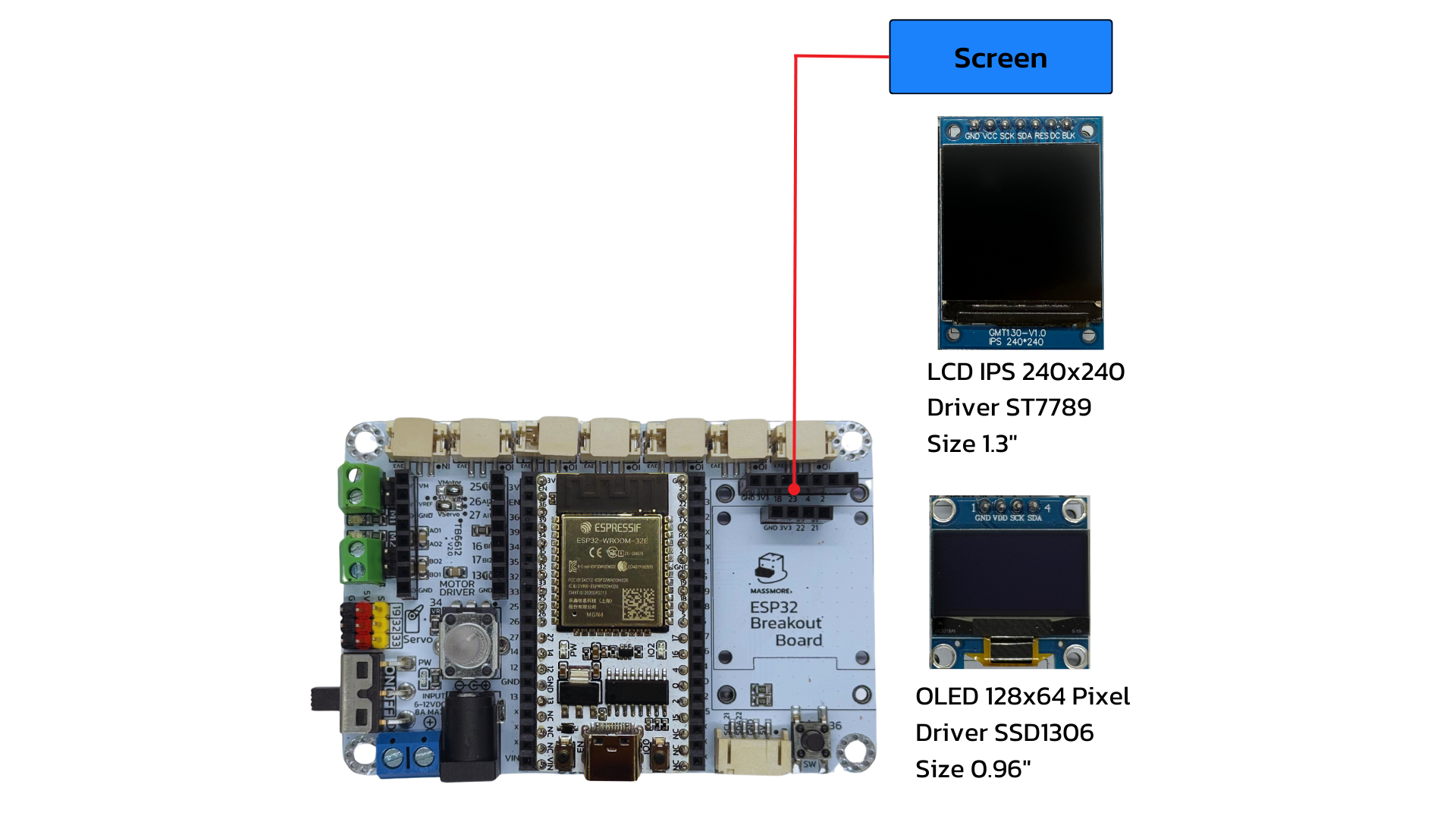
ตัวบอร์ดรองรับการใช้งานหน้าจอทั้งสองรูปแบบโดยมีตัวอย่างดังนี้
ตัวอย่างที่ 3 การแสดงผลจาก INPUT ไปที่หน้าจอ LCD 240x240 ST7789
อุปกรณ์ที่ใช้ในโปรเจกต์
บอร์ด ESP32 38PIN Massmore
หน้าจอ LCD 240×240 ST7789 1.3 นิ้ว
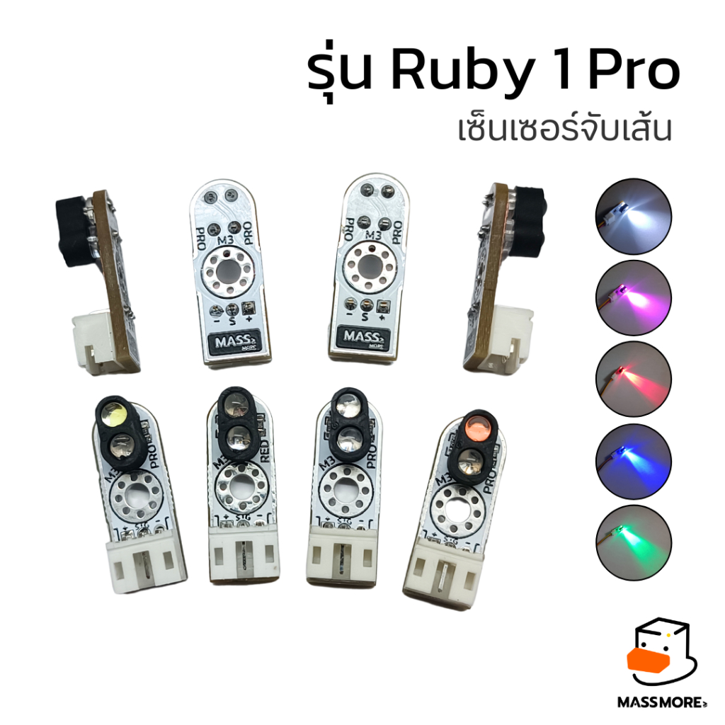
- เซ็นเซอร์จับเส้น Massmore (รุ่นไหนก็ได้)
Arduino IDE Code
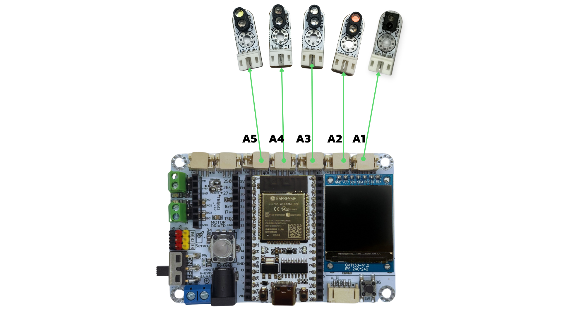
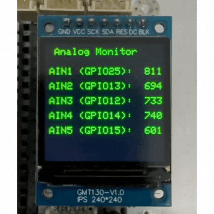
โปรแกรม ESP32 อ่านค่า Analog 5 ช่อง และแสดงบนจอ LCD ST7789 (240×240) โดยใช้ไลบรารี TFT_eSPI
					#include <TFT_eSPI.h>  // ใช้ไลบรารี TFT_eSPI (ตั้งค่าใน User_Setup.h ก่อนใช้งาน)

TFT_eSPI tft = TFT_eSPI();  // สร้างอ็อบเจ็กต์สำหรับควบคุมจอ

// กำหนดขา Analog Input
const int analogPins[5] = {13, 12, 14, 15, 5};
int analogValues[5];  // ตัวแปรเก็บค่าที่อ่านได้

void setup() {
  Serial.begin(115200);

  // เริ่มต้นจอแสดงผล
  tft.init();
  tft.setRotation(0);  // หมุนหน้าจอได้ 0-3 แล้วแต่การติดตั้ง
  tft.fillScreen(TFT_BLACK);  // เคลียร์หน้าจอด้วยสีดำ
  tft.setTextSize(2);
  tft.setTextColor(TFT_GREEN, TFT_BLACK);  // ตัวอักษรสีเขียว พื้นหลังดำ

  // แสดงข้อความเริ่มต้น
  tft.setCursor(20, 10);
  tft.println("Analog Monitor");
  delay(1000);
}

void loop() {
  // อ่านค่า Analog ทุกช่อง
  for (int i = 0; i < 5; i++) {
    analogValues[i] = analogRead(analogPins[i]);
  }

  // เคลียร์พื้นหลังบางส่วนก่อนเขียนค่าใหม่
  tft.fillRect(0, 40, 240, 200, TFT_BLACK);

  // แสดงผลค่า Analog
  for (int i = 0; i < 5; i++) {
    tft.setCursor(10, 50 + i * 30);
    tft.printf("AIN%d (GPIO%d): %4d", i + 1, analogPins[i], analogValues[i]);
  }

  delay(500);  // หน่วงเวลา 0.5 วินาที
}
อธิบายการทำงานของโค้ด
1. การเรียกใช้ไลบรารี
#include <TFT_eSPI.h>
ใช้ไลบรารี TFT_eSPI สำหรับควบคุมจอ ST7789
ไลบรารีนี้ต้องตั้งค่าขา GPIO ในไฟล์
User_Setup.hให้ตรงกับบอร์ดก่อนใช้งาน
2. การกำหนดตัวแปรสำคัญ
					TFT_eSPI tft = TFT_eSPI();  // สร้างวัตถุควบคุมจอ
const int analogPins[5] = {13, 12, 14, 15, 5}; // GPIO สำหรับอ่าน Analog
int analogValues[5]; // ตัวแปรเก็บค่าที่อ่านได้จากแต่ละช่อง
กำหนดขา GPIO 5 ขา ที่จะใช้สำหรับรับค่า Analog จากอุปกรณ์ภายนอก (เช่น VR, เซ็นเซอร์)
สร้างตัวแปร array สำหรับเก็บค่า analogRead แต่ละช่อง
3. การตั้งค่าจอและ Serial Monitor ใน setup()
					tft.init();             // เริ่มต้นหน้าจอ
tft.setRotation(0);     // หมุนจอตามการใช้งานจริง (0-3)
tft.fillScreen(TFT_BLACK); // เคลียร์หน้าจอด้วยสีดำ
tft.setTextSize(2);     // ขนาดตัวอักษร
tft.setTextColor(TFT_GREEN, TFT_BLACK); // สีตัวอักษร (เขียวพื้นดำ)

tft.setCursor(20, 10);
tft.println("Analog Monitor");
เริ่มต้นหน้าจอ LCD และตั้งค่าการแสดงผล เช่น สี ขนาด ฟอนต์
แสดงข้อความต้อนรับ “Analog Monitor”
4. อ่านค่า Analog และแสดงผลใน loop()
					for (int i = 0; i < 5; i++) {
  analogValues[i] = analogRead(analogPins[i]);
}
วนลูปอ่านค่าจากขา GPIO แต่ละขา (เป็นค่าตัวเลข 0-4095 บน ESP32)
tft.fillRect(0, 40, 240, 200, TFT_BLACK);
ลบพื้นที่แสดงผลเดิม (เพื่อล้างข้อความก่อนพิมพ์ค่าใหม่)
					for (int i = 0; i < 5; i++) {
  tft.setCursor(10, 50 + i * 30);
  tft.printf("AIN%d (GPIO%d): %4d", i + 1, analogPins[i], analogValues[i]);
}
วนลูปแสดงค่าที่อ่านได้ลงบนหน้าจอ
จะแสดงชื่อช่อง AIN1-AIN5 พร้อมกับเลข GPIO และค่าที่อ่านได้
delay(500);
หน่วงเวลา 0.5 วินาทีเพื่อให้อ่านง่าย ไม่กระพริบไวเกินไป
สรุป
โปรแกรมนี้ใช้ ESP32 อ่านค่า Analog จาก GPIO 5 ช่อง แล้วนำไปแสดงผลบนจอ LCD ST7789 ขนาด 240×240 พิกเซล ด้วยไลบรารี TFT_eSPI โดยแสดงผลค่าที่ได้แบบเรียลไทม์พร้อมข้อความกำกับอย่างชัดเจน
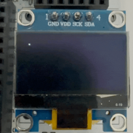
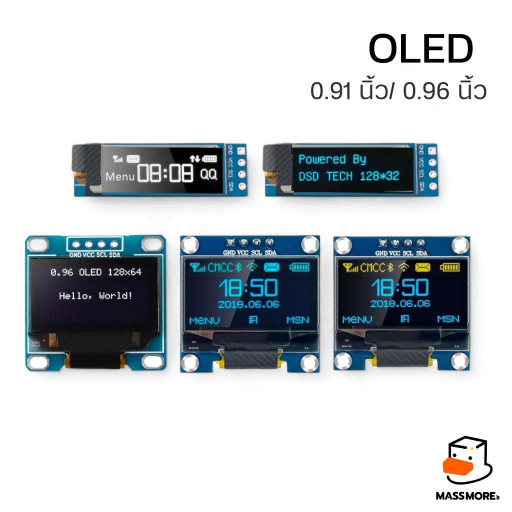
ตัวอย่างที่ 4 การแสดงผลหน้าจอ OLED 128x64 Pixel Driver SSD1306 Size 0.96"
อุปกรณ์ที่ใช้ในโปรเจกต์
บอร์ด ESP32 38PIN Massmore
หน้าจอ OLED 128×64 Pixel Driver SSD1306 Size 0.96″
Arduino IDE Code
โปรแกรมนี้เขียนด้วยภาษา Arduino โดยมีจุดประสงค์เพื่อแสดงผลหน้าจอ ผ่านขา GPIO ของ ESP32 โดยใช้ I2C Port
*** จำเป็นต้องติดตั้ง Library Adafruit_GFX.h และ Adafruit_SSD1306.h
					#include <SPI.h>
#include <Wire.h>
#include <Adafruit_GFX.h>
#include <Adafruit_SSD1306.h>

#define SCREEN_WIDTH 128 // OLED display width, in pixels
#define SCREEN_HEIGHT 64 // OLED display height, in pixels

// Declaration for an SSD1306 display connected to I2C (SDA, SCL pins)
#define OLED_RESET     -1 // Reset pin # (or -1 if sharing Arduino reset pin)
Adafruit_SSD1306 display(SCREEN_WIDTH, SCREEN_HEIGHT, &Wire, OLED_RESET);

#define NUMFLAKES     10 // Number of snowflakes in the animation example

#define LOGO_HEIGHT   16
#define LOGO_WIDTH    16
static const unsigned char PROGMEM logo_bmp[] =
{ B00000000, B11000000,
  B00000001, B11000000,
  B00000001, B11000000,
  B00000011, B11100000,
  B11110011, B11100000,
  B11111110, B11111000,
  B01111110, B11111111,
  B00110011, B10011111,
  B00011111, B11111100,
  B00001101, B01110000,
  B00011011, B10100000,
  B00111111, B11100000,
  B00111111, B11110000,
  B01111100, B11110000,
  B01110000, B01110000,
  B00000000, B00110000 };

void setup() {
  Serial.begin(115200);

  // SSD1306_SWITCHCAPVCC = generate display voltage from 3.3V internally
  if(!display.begin(SSD1306_SWITCHCAPVCC, 0x3C)) {
    Serial.println(F("SSD1306 allocation failed"));
    for(;;); // Don't proceed, loop forever
  }

  // Show initial display buffer contents on the screen --
  // the library initializes this with an Adafruit splash screen.
  display.display();
  delay(2000); // Pause for 2 seconds

  // Clear the buffer
  display.clearDisplay();

  // Draw a single pixel in white
  display.drawPixel(10, 10, WHITE);

  // Show the display buffer on the screen. You MUST call display() after
  // drawing commands to make them visible on screen!
  display.display();
  delay(2000);
  // display.display() is NOT necessary after every single drawing command,
  // unless that's what you want...rather, you can batch up a bunch of
  // drawing operations and then update the screen all at once by calling
  // display.display(). These examples demonstrate both approaches...

  testdrawline();      // Draw many lines

  testdrawrect();      // Draw rectangles (outlines)

  testfillrect();      // Draw rectangles (filled)

  testdrawcircle();    // Draw circles (outlines)

  testfillcircle();    // Draw circles (filled)

  testdrawroundrect(); // Draw rounded rectangles (outlines)

  testfillroundrect(); // Draw rounded rectangles (filled)

  testdrawtriangle();  // Draw triangles (outlines)

  testfilltriangle();  // Draw triangles (filled)

  testdrawchar();      // Draw characters of the default font

  testdrawstyles();    // Draw 'stylized' characters

  testscrolltext();    // Draw scrolling text

  testdrawbitmap();    // Draw a small bitmap image

  // Invert and restore display, pausing in-between
  display.invertDisplay(true);
  delay(1000);
  display.invertDisplay(false);
  delay(1000);

  testanimate(logo_bmp, LOGO_WIDTH, LOGO_HEIGHT); // Animate bitmaps
}

void loop() {
}

void testdrawline() {
  int16_t i;

  display.clearDisplay(); // Clear display buffer

  for(i=0; i<display.width(); i+=4) {
    display.drawLine(0, 0, i, display.height()-1, WHITE);
    display.display(); // Update screen with each newly-drawn line
    delay(1);
  }
  for(i=0; i<display.height(); i+=4) {
    display.drawLine(0, 0, display.width()-1, i, WHITE);
    display.display();
    delay(1);
  }
  delay(250);

  display.clearDisplay();

  for(i=0; i<display.width(); i+=4) {
    display.drawLine(0, display.height()-1, i, 0, WHITE);
    display.display();
    delay(1);
  }
  for(i=display.height()-1; i>=0; i-=4) {
    display.drawLine(0, display.height()-1, display.width()-1, i, WHITE);
    display.display();
    delay(1);
  }
  delay(250);

  display.clearDisplay();

  for(i=display.width()-1; i>=0; i-=4) {
    display.drawLine(display.width()-1, display.height()-1, i, 0, WHITE);
    display.display();
    delay(1);
  }
  for(i=display.height()-1; i>=0; i-=4) {
    display.drawLine(display.width()-1, display.height()-1, 0, i, WHITE);
    display.display();
    delay(1);
  }
  delay(250);

  display.clearDisplay();

  for(i=0; i<display.height(); i+=4) {
    display.drawLine(display.width()-1, 0, 0, i, WHITE);
    display.display();
    delay(1);
  }
  for(i=0; i<display.width(); i+=4) {
    display.drawLine(display.width()-1, 0, i, display.height()-1, WHITE);
    display.display();
    delay(1);
  }

  delay(2000); // Pause for 2 seconds
}

void testdrawrect(void) {
  display.clearDisplay();

  for(int16_t i=0; i<display.height()/2; i+=2) {
    display.drawRect(i, i, display.width()-2*i, display.height()-2*i, WHITE);
    display.display(); // Update screen with each newly-drawn rectangle
    delay(1);
  }

  delay(2000);
}

void testfillrect(void) {
  display.clearDisplay();

  for(int16_t i=0; i<display.height()/2; i+=3) {
    // The INVERSE color is used so rectangles alternate white/black
    display.fillRect(i, i, display.width()-i*2, display.height()-i*2, INVERSE);
    display.display(); // Update screen with each newly-drawn rectangle
    delay(1);
  }

  delay(2000);
}

void testdrawcircle(void) {
  display.clearDisplay();

  for(int16_t i=0; i<max(display.width(),display.height())/2; i+=2) {
    display.drawCircle(display.width()/2, display.height()/2, i, WHITE);
    display.display();
    delay(1);
  }

  delay(2000);
}

void testfillcircle(void) {
  display.clearDisplay();

  for(int16_t i=max(display.width(),display.height())/2; i>0; i-=3) {
    // The INVERSE color is used so circles alternate white/black
    display.fillCircle(display.width() / 2, display.height() / 2, i, INVERSE);
    display.display(); // Update screen with each newly-drawn circle
    delay(1);
  }

  delay(2000);
}

void testdrawroundrect(void) {
  display.clearDisplay();

  for(int16_t i=0; i<display.height()/2-2; i+=2) {
    display.drawRoundRect(i, i, display.width()-2*i, display.height()-2*i,
      display.height()/4, WHITE);
    display.display();
    delay(1);
  }

  delay(2000);
}

void testfillroundrect(void) {
  display.clearDisplay();

  for(int16_t i=0; i<display.height()/2-2; i+=2) {
    // The INVERSE color is used so round-rects alternate white/black
    display.fillRoundRect(i, i, display.width()-2*i, display.height()-2*i,
      display.height()/4, INVERSE);
    display.display();
    delay(1);
  }

  delay(2000);
}

void testdrawtriangle(void) {
  display.clearDisplay();

  for(int16_t i=0; i<max(display.width(),display.height())/2; i+=5) {
    display.drawTriangle(
      display.width()/2  , display.height()/2-i,
      display.width()/2-i, display.height()/2+i,
      display.width()/2+i, display.height()/2+i, WHITE);
    display.display();
    delay(1);
  }

  delay(2000);
}

void testfilltriangle(void) {
  display.clearDisplay();

  for(int16_t i=max(display.width(),display.height())/2; i>0; i-=5) {
    // The INVERSE color is used so triangles alternate white/black
    display.fillTriangle(
      display.width()/2  , display.height()/2-i,
      display.width()/2-i, display.height()/2+i,
      display.width()/2+i, display.height()/2+i, INVERSE);
    display.display();
    delay(1);
  }

  delay(2000);
}

void testdrawchar(void) {
  display.clearDisplay();

  display.setTextSize(1);      // Normal 1:1 pixel scale
  display.setTextColor(WHITE); // Draw white text
  display.setCursor(0, 0);     // Start at top-left corner
  display.cp437(true);         // Use full 256 char 'Code Page 437' font

  // Not all the characters will fit on the display. This is normal.
  // Library will draw what it can and the rest will be clipped.
  for(int16_t i=0; i<256; i++) {
    if(i == '\n') display.write(' ');
    else          display.write(i);
  }

  display.display();
  delay(2000);
}

void testdrawstyles(void) {
  display.clearDisplay();

  display.setTextSize(1);             // Normal 1:1 pixel scale
  display.setTextColor(WHITE);        // Draw white text
  display.setCursor(0,0);             // Start at top-left corner
  display.println(F("Hello, world!"));

  display.setTextColor(BLACK, WHITE); // Draw 'inverse' text
  display.println(3.141592);

  display.setTextSize(2);             // Draw 2X-scale text
  display.setTextColor(WHITE);
  display.print(F("0x")); display.println(0xDEADBEEF, HEX);

  display.display();
  delay(2000);
}

void testscrolltext(void) {
  display.clearDisplay();

  display.setTextSize(2); // Draw 2X-scale text
  display.setTextColor(WHITE);
  display.setCursor(10, 0);
  display.println(F("scroll"));
  display.display();      // Show initial text
  delay(100);

  // Scroll in various directions, pausing in-between:
  display.startscrollright(0x00, 0x0F);
  delay(2000);
  display.stopscroll();
  delay(1000);
  display.startscrollleft(0x00, 0x0F);
  delay(2000);
  display.stopscroll();
  delay(1000);
  display.startscrolldiagright(0x00, 0x07);
  delay(2000);
  display.startscrolldiagleft(0x00, 0x07);
  delay(2000);
  display.stopscroll();
  delay(1000);
}

void testdrawbitmap(void) {
  display.clearDisplay();

  display.drawBitmap(
    (display.width()  - LOGO_WIDTH ) / 2,
    (display.height() - LOGO_HEIGHT) / 2,
    logo_bmp, LOGO_WIDTH, LOGO_HEIGHT, 1);
  display.display();
  delay(1000);
}

#define XPOS   0 // Indexes into the 'icons' array in function below
#define YPOS   1
#define DELTAY 2

void testanimate(const uint8_t *bitmap, uint8_t w, uint8_t h) {
  int8_t f, icons[NUMFLAKES][3];

  // Initialize 'snowflake' positions
  for(f=0; f< NUMFLAKES; f++) {
    icons[f][XPOS]   = random(1 - LOGO_WIDTH, display.width());
    icons[f][YPOS]   = -LOGO_HEIGHT;
    icons[f][DELTAY] = random(1, 6);
    Serial.print(F("x: "));
    Serial.print(icons[f][XPOS], DEC);
    Serial.print(F(" y: "));
    Serial.print(icons[f][YPOS], DEC);
    Serial.print(F(" dy: "));
    Serial.println(icons[f][DELTAY], DEC);
  }

  for(;;) { // Loop forever...
    display.clearDisplay(); // Clear the display buffer

    // Draw each snowflake:
    for(f=0; f< NUMFLAKES; f++) {
      display.drawBitmap(icons[f][XPOS], icons[f][YPOS], bitmap, w, h, WHITE);
    }

    display.display(); // Show the display buffer on the screen
    delay(200);        // Pause for 1/10 second

    // Then update coordinates of each flake...
    for(f=0; f< NUMFLAKES; f++) {
      icons[f][YPOS] += icons[f][DELTAY];
      // If snowflake is off the bottom of the screen...
      if (icons[f][YPOS] >= display.height()) {
        // Reinitialize to a random position, just off the top
        icons[f][XPOS]   = random(1 - LOGO_WIDTH, display.width());
        icons[f][YPOS]   = -LOGO_HEIGHT;
        icons[f][DELTAY] = random(1, 6);
      }
    }
  }
}
สรุป
เริ่มต้นใช้งานจอ OLED
ตั้งค่าการเชื่อมต่อจอผ่าน I2C ที่ Address
0x3Cล้างหน้าจอ (clear)
แสดงกราฟิกต่าง ๆ ทีละขั้น
วาดเส้น (line), สี่เหลี่ยม (rectangle), วงกลม (circle), สามเหลี่ยม (triangle)
วาดตัวอักษรธรรมดา และแบบสไตล์ต่าง ๆ
แสดงข้อความแบบ scroll ซ้ายขวา
แสดงรูปภาพ (bitmap)
แสดงภาพเคลื่อนไหว (animation) แบบเกล็ดหิมะตกลงหน้าจอ
Development Board - บอร์ดพัฒนา
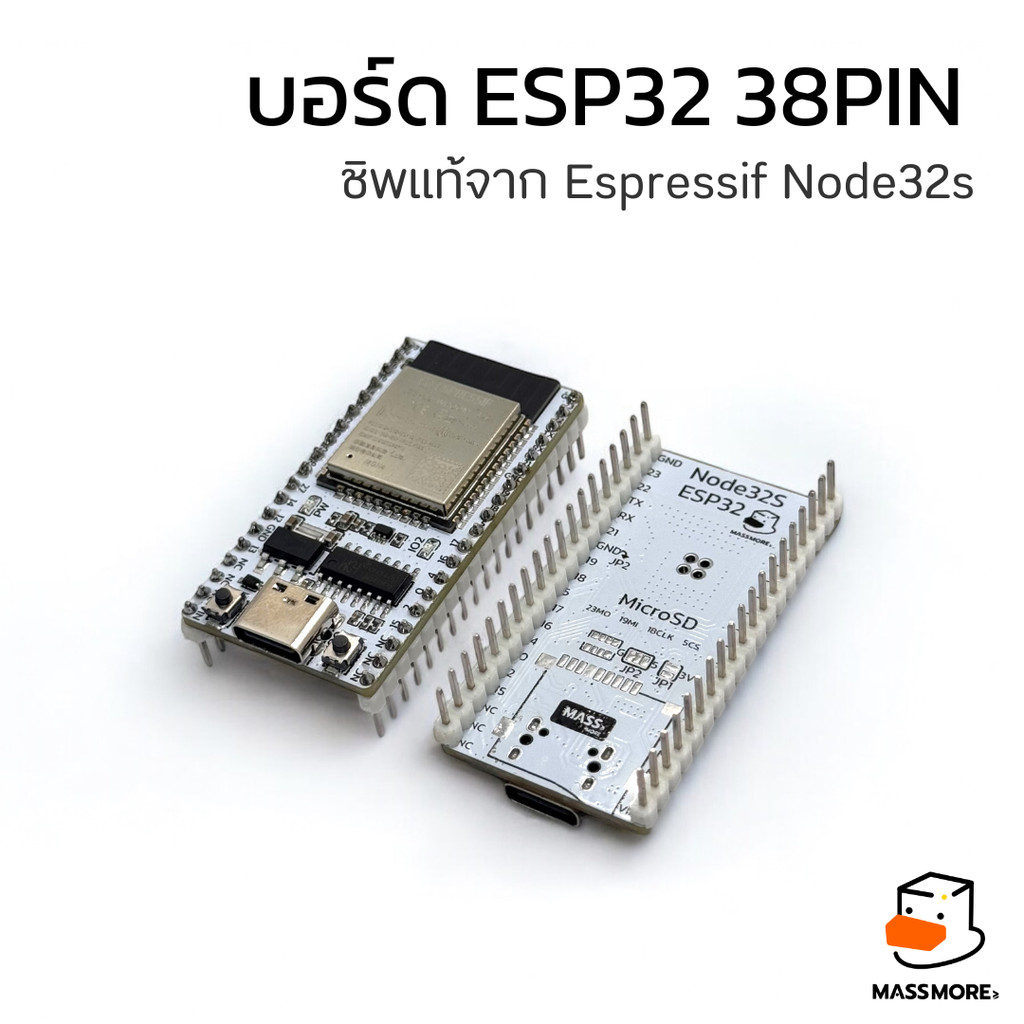
บอร์ด ESP32 38PIN ชิพแท้จาก Espressif Node32s ESP32S USB Type-C Massmore
฿350.00
Development Board - บอร์ดพัฒนา
บอร์ดขยาย หุ่นยนต์ Robot ESP32 38PIN Breakout Board บอร์ดทดลอง Prototype ชุดฝึก Arduino Massmore
฿590.00
- เลือกรูปแบบ This product has multiple variants. The options may be chosen on the product page
Robotics - หุ่นยนต์
เซ็นเซอร์จับเส้น Sensor Line Follower เซ็นเซอร์หุ่นยนต์วิ่งตามเส้น Phototransistor รุ่น Ruby
฿49.00
เลือกรูปแบบ This product has multiple variants. The options may be chosen on the product page
- เลือกรูปแบบ This product has multiple variants. The options may be chosen on the product page
Displays - หน้าจอ
โมดูลหน้าจอ OLED ขนาด 0.91 0.96 นิ้ว I2C Display Module Driver SSD1306 12864 128x64 Pixel
฿65.00 – ฿69.00Price range: ฿65.00 through ฿69.00
เลือกรูปแบบ This product has multiple variants. The options may be chosen on the product page